|
Click on any picture to view a larger image. Visit Crichton Miller's Website The Cross Revealed - Part 2 Crichton Edward McGregor Miller
The proposal and thesis is based upon the discoveries and calculations of the author, whilst working on the proposal that the Celtic cross was an instrument derived from the astrolabe and quadrant. That the Celtic cross was used as a spherical measuring instrument for the purposes of navigation, astronomy, surveying, cartography and time keeping. [Update - The instrument was granted a Patent by The United Kingdom Patents Office under Patent No GB 2344887 after extensive world wide searches and publications. The Patent was granted in November 2000 . The patent was granted because the instrument was not "obvious" in that it had two unique features not available to any instrument in the world today. 1.The ability to take sidereal (horizontal) angular observations. 2.The use of a fulcrum for steadiness and accuracy.] This work, to all intents and purposes, has been peer reviewed and published accordingly. Since there is, and has been, much debate amongst groups of academics over the ancient methods of surveying the pyramids at Giza. I. How did the ancient architects survey and lay out the constructions? 2. How did the architects achieve alignment? 3. Were the alignments achieved by solar or stellar observation? 4. How did the architects achieve such accuracy? 5. What instrument did they use? It is known that the ancient Egyptians used plumb line technology in many areas, particularly in weights and measures. This is depicted in many friezes and was also used in surveying, with the instruments known as the Bay and Merkhet. (see footnotes) What has not been found to date, is an instrument capable of acting as an inclinometer or modern theodolite / sextant. Not only that, but one that is accurate to degrees and fractions of degrees. Degrees are broken down into minutes and seconds of arc. One minute of arc is equal to one nautical mile on the meridian. 1. The proposal is that the pyramid of Khufu was surveyed with an instrument capable of an accuracy of 3 minutes of arc. 2. That the evidence of the use of this instrument, is not only in the constructions but that the author has found evidence of the actual artifact. The Evidence
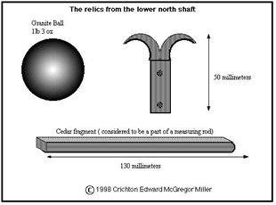
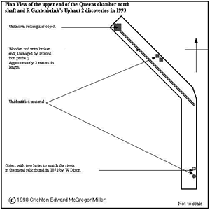
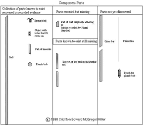
Charles Piazzi Smyth in his 1878 book "The Great Pyramid" recorded the relics found in the north shaft of the Queens chamber by Dixon and Grant. These items were found in the hermetically sealed north shaft broken into by a Bill Grundy under the direction of W Dixon. The relics were sent to Piazzi Smyth in a cigar box where they were recorded in his diary with accompanying drawings and sketches. Two of the objects are now in the British Museum. The 1872 items consisted of; A slat or rod of cedar wood about 13 centimeters long (part of a measuring rod) A granite ball weighing 1lb 3 ounces A bronze/copper hook type of instrument, 5 centimeters long, with a part of a wooden handle still attached. No further examination of the shafts in the Queens chamber had been carried out until 1993, when Rudolf Gantenbrink developed a remarkable robot known as Uphaut 2 to explore the shafts and to install a ventilation system in the Pyramid of Cheops, designed to reduce humidity within the pyramid. He was subsequently, to make the most accurate internal survey of the shafts to date. This work was undertaken on behalf of the Egyptian Government with the approval of DR Zahi Hawass. The operation was a success and a credit to Rudolf Gantenbrink. The discoveries made were remarkable and increased understanding of the construction of the pyramid. The robot is now in the British museum and the story of this work is public knowledge. What is relevant to my theory is that it appears that in 1872, Waynman Dixon explored the northern shaft with an extendible iron rod. There can be seen an object that appears to look like a rectangle of wood or metal, with two corresponding holes to match the rivets on the metal instrument. Rudolf Gantenbrink was unable to explore the shaft further for technical reasons. Having collated the information available from the relics found in 1872 and those seen in the shaft in 1993, theoretical reconstruction of the instrument can be achieved. The items are as follows: 1. Plumb bob 2. Fragment of scale rule (now missing but recorded by Piazzi Smyth) 3. Bronze or copper fork with fixing rivets attached.
1993 objects: 1. A piece of wood with holes that match the rivets on the bronze item. 2. A 2-meter plus length of wood resembling a staff with a portion missing. 3. Various pieces of unidentified material, located in two areas of the shaft. 4. A large rectangular object can be seen at the upper end of the shaft attached to the 2-meter length of wood. With this component list, it is possible to assemble the known parts in a logical format.
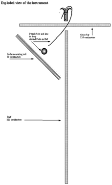
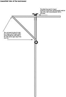
1. The metal fork appears to be designed to attach to one end of the long staff by a half housed joint held by the two rivets on one side of the hook. 2. The plumb line is looped over the fork, on the top of the staff, by way of a slipknot. The working end returning over the side of the fork opposite to the scale, this allows the line to cut the apex of the joint between the cross arm and the staff precisely. 3. A pouch or net is fixed to the opposite end of the plumb line, to hold the plumb bob. 4. A cross bar is mounted on the fork, at right angles to the staff and fixed with the remaining two rivets at the front of the instrument. (I believe that this is the purpose of the object with two corresponding holes still in the shaft) 5. One end of a measuring rod is fixed at 45o to one arm of the cross bar. 6. The other end of the measuring rod is fixed at 45o to the upright of the staff.
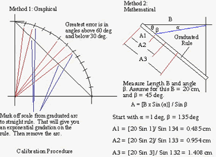
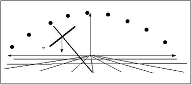
Measuring Rods Proof that the Egyptian's had sufficient knowledge of decimals and degrees to allow construction of the measuring rod, has already been proved and published by Sir William Flanders Petrie, when he surveyed the Pyramid of Khufu, where he stated that the Royal Cubit measured 523.95 millimeters or 20.6 inches. It was established that Fourth Dynasty builders divided the cubit into decimals. Sir William also named a unit of measurement used at Giza as a digit, which is constantly accurate to one tenth of a millimeter. 1.75752 cubits = 9180 digits = 918 millimeters = 90 centimeters approximately. Sufficiently close enough for centimeters and millimeters to represent degrees and minutes for the purposes of this experiment. Exponential Scale Extreme accuracy for the time of three arc minutes would be achieved by the development of an exponential scale. This is achieved by drawing lines from the center point of a circle
outward, through the rule. This can be seen in the next figure, kindly
provided by Jim Bowles. Evidence of tools. Sir William Petrie also established that no tools were to be discovered and described the reasons why. The tools were sacred and belonged to the Royal Family; losing one was a serious crime and could have resulted in the loss of life for the unfortunate individual to blame. The use of the types of tools employed in the construction was through analysis of the marks on the stone, therefore it was possible to deduce that there was metal in the tools used by the evidence left in the cuts. According to Sir William Flanders Petrie, bronze and copper saws and drills of various designs were employed. Some with precious stones for tips and accordingly would have been very valuable. Secrecy. I believe that these tools were owned by Master Craftsmen, practicing in Guilds and that their tools and skills were precious to them, as it was to later generations of craftsmen employed during the Great Cathedral building age in Europe. I believe that this instrument is tangible proof of the Ancient Egyptians depth of knowledge in the disciplines of astronomy, surveying and navigation hitherto underestimated. I believe that this knowledge may have been practiced by members of craft guilds, in secret, right up to the age of Cathedral building in Europe. The knowledge may have been kept secret for two reasons. 1. That the Trade Guild or Society members were sworn to secrecy after or during their apprenticeship, so as to protect their knowledge from the uninitiated. 2. That there was persecution even to death by the religious powers during certain historical periods, who would allow no dealing with astronomy or other "occult practices". I believe that the Christian Cross originated from an instrument used by the craftsmen in ancient Egypt and possibly other more ancient civilizations such as the Neolithic Peoples. I think that the relics discovered by Dixon in the Queens chamber, were part of an originally complete instrument that had been sealed into the pyramid by the architects, in the same manner that masons and craftsmen made their mark on their stone masterpieces. This tradition is carried forward to this day and is usually found in foundation and corner stones of buildings. I intend to show that in the skilled hands of a skilled and knowledgeable operator, this simple instrument can be used for the following purposes:
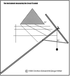
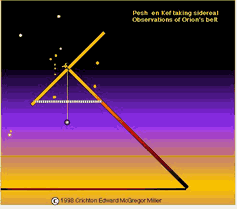
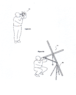
1. The Instrument can be used to take remarkably accurate astronomical measurements. 2. Measuring distances for chart and map making including measuring the circumference of the Earth. To an accuracy of 3 arc minutes. 3. The Instrument can be used for Civil engineering projects such as surveying and construction. 4.Timekeeping and the calendar upkeep are possible with this instrument. 5.Navigation including latitude to an accuracy of 3 nautical miles on a handheld version. This diagram shows the unique ability of the instrument to take sidereal angular measurements of the movement of astronomical bodies. With the knowledge of local time coupled with a rudimentary knowledge of astronomy, it is possible to find both latitude and longitude with this instrument. This example shows the use of the bronze fork If an observer uses the cleft in the fork to sight the star at night, it would be difficult to see without a polished and reflective surface. This example of a cross type of instrument shows how linear angles can be found with the addition of an effective scale set at 45 degrees to the upright and cross bars. The tripod at the foot of the assembly, adds stability.
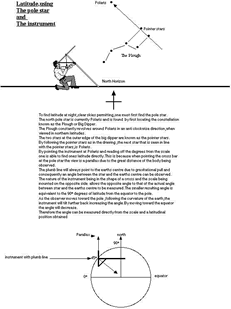
The illustration was taken from UK Patent No. GB 2 344 654 A The following example is a tutorial for finding latitude with the instrument using the current pole star of Polaris
This figure shows how accurately a modern observer can find latitude with this instrument. Polaris was not the pole star at the time of the building of the Pyramid of Khufu. Because of the effect of precession, the polar region has moved to its present position. It is, however, possible to find a meridian with this instrument, both day and night. The system is by interpolating the declination of an astronomical body with the use of equal altitude observations. This is only possible with an instrument of this type.
Solar observations The instrument is capable of taking solar observations and measuring declination and Hour angles. This is achieved by indirectly viewing the sun. The instrument is directed at the sun and the shadow is projected onto a horizontal surface. By aligning the cross bar toward the sun an accurate shadow image can be read, and the degrees read from the scale.
The Author is only to happy to answer relevant questions.
The author © 1998 - 2000 Crichton E M Miller
c-miller@dircon.co.uk Bibliography The Merkhet. Fred Hoyl. 1962 http://scivis.com/AC/inst/plumb.html
Crichton Edward McGregor Miller hereby
assert and give notice of my right under section 77 Visit Crichton Miller's Website
|

